Tracker Parameterization
Tracker Parameterization#
Now, that we know enough about the tracker, possible constraints, we can now parameterize the tracker geometry. Parameterizing the detector geometry is very crucial since, one can identify the free parameters (search parameter) of the design problem. Parameterization allows to effectively compute the constraints along with generating design parameters that do not overlap with each other. This is very crucial as GEANT4 gives unphysical results when there are detector overlaps.
Parameterizing helps us define the design problem with defining the search space, defining the constraints (Intelligently encode constraints), and to perform independent checks on feasibility of the design.
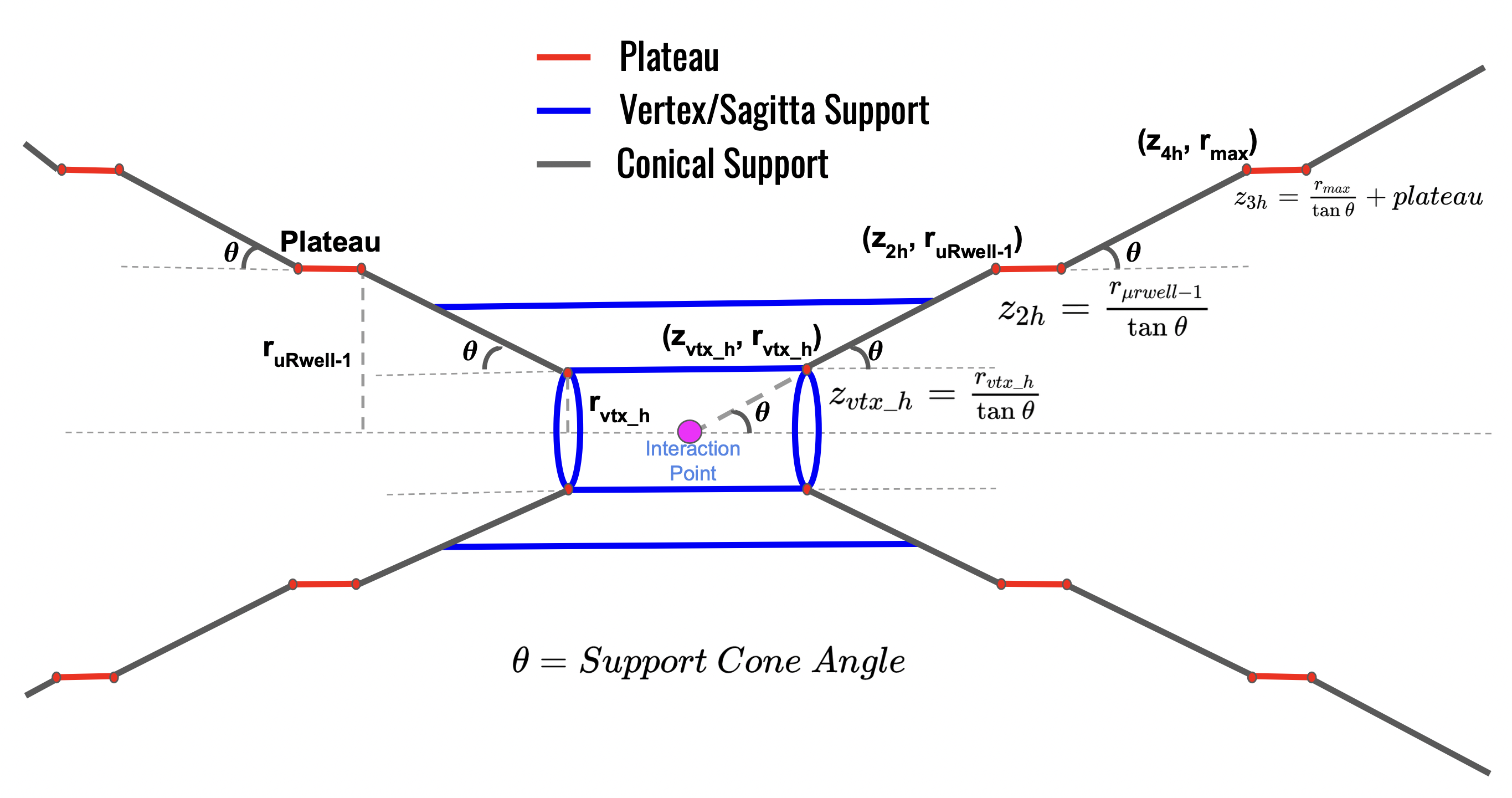
The parameterization that was followed during the proposal mainly focusses on the support cone structure, By parameterizing the support cone, the other subdetector systems are made to be compatabile within the support cone structure as shown in the figure Fig. 6
Tip
If keeping all material in one place is intended we can

Fig. 6 The inner tracker support is characterized by five variables: \(\theta\) (the angle of projection of the support cone structure), \(r_{vtx}\) (radius of vertex support structure), \(r_{\mu rwell-1}\) \(\mu\)Rwell-1 radius, plateau length, \(r_{max}\) maximum allowed radius of inner tracker)#
Detailed explanation on parameterizing the subdetector system using this parameterization is given in [2]. A brief summary is given below
Angle of Support :
This is the angle which defines the angle of the support cone.
This is a design parameter that is considered for optimization.
Vertex Layers:
The vertex cylinder consists of strips which are made of pixels, where the individual sensor unit cell size is 17.8 mm \(\times\) 30.0 mm.
The vertex system is fixed during optimization.
The support structure for the vertex layer is calculated based on the angle of the support cone.
Sagitta Layers:
The length of the sagitta layers are fixed.
The radius of the sagitta layer depends on the angle of the cone and its length itself as \(r_{sagitta} = \frac{l_{sagitta}}{2}\tan{\theta}\)
Now, Radius of the sagitta layers also cannot be arbitary as mentioned in [soft constraints]. The constraint on the sagitta layer radii are calculated for the given design point.
Tip
This is the advantage of the parameterization as these dependent quantities which do not enter the optimization directly but dependent on quantities that are optimized can be calculated.
The constraints are also calculated explicitly using this parameterization.
\(\mu\)Rwell Layers
There are 3 \(\mu\)Rwell layers in the barrel region.
\(\mu\)Rwell layer-1 is considered for optimization. The radius of the \(\mu\)Rwell is optimized
The length of the \(\mu\)Rwell cylinders are calculated based on the angle of the cone and the radius of the cylinder as shown in the figure Fig. 6. A plateau of 5cm is given to accommodate support rings of the \(\mu\)Rwell.
FST/EST disks
\(R_{min}\) of the disks must be compatible with the beam pipe envelope which increases in radius as a function of \(z\).
\(R_{out}\) of the disks is parametrized to be compatible with the support cone structure shown in Fig. 6 which has an angle \(\theta\) that is variable in the projective design and fixed in the non-projective case.
To account for full \(\eta\) coverage, A FST/EST disk is placed each time there is a change of slope.
[Soft constraints] corresponding to the EST/FST disks are now calculated.
ETTL/FTTL ToF disks
\(R_{min}\) of the disks must be compatible with the beam pipe envelope which increases in radius as a function of \(z\).
\(R_{out}\) of the disks is parametrized to be compatible with the support cone structure shown in Fig. 6 which has an angle \(\theta\) that is variable in the projective design and fixed in the non-projective case.
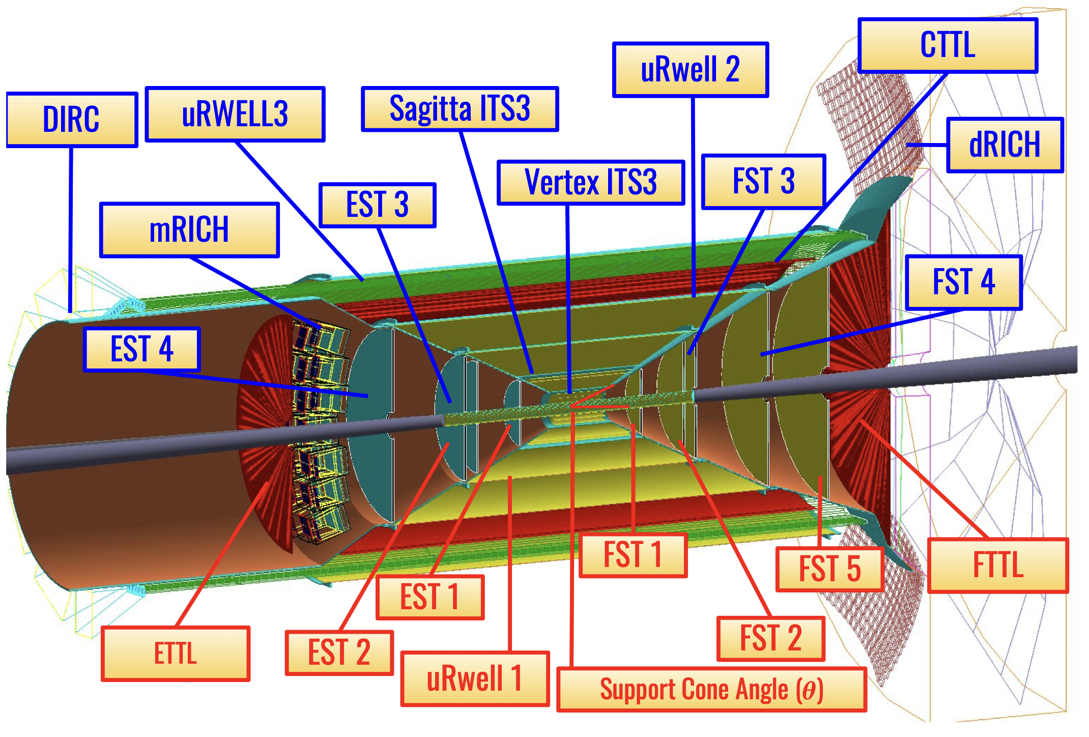
Following this parameterization, 9 parameters were identified as design parameters to optimize, The figure Fig. 7 shows the detector subsyste that was optimized during Phase-II of optimization and the table below summarizes the design parameters and its corresponding search ranges.
Design Parameter |
Range |
|---|---|
Angle (Support Cone) |
[25.0\(^\text{o}\), 30.0\(^\text{o}\)] |
\(\mu\)RWELL 1 (Inner) Radius |
[25.0, 45.0 cm] |
ETTL \(z\) position |
[-171.0, -161.0 cm] |
EST 2 \(z\) position |
[45, 100 cm] |
EST 1 \(z\) position |
[35, 50 cm] |
FST 1 \(z\) position |
[35, 50 cm] |
FST 2 \(z\) position |
[45, 100 cm] |
FST 5 \(z\) position |
[100, 150 cm] |
FTTL \(z\) postion |
[156, 183 cm] |

Fig. 7 Parameterized Tracking system. Labels in red indicate the sub-detector systems that were optimized, while the labels in blue are the sub-detector systems that were kept fixed due to geometrical constraint#
